11
全部商品分类

 毕业设计辅助工具_免费论文文案文章修改神器_毕业设计辅助软件_论文查重...¥0
 solidworks2018 中文版¥0
 CA6140车床拨叉831006零件夹具设计说明书——9页...¥0
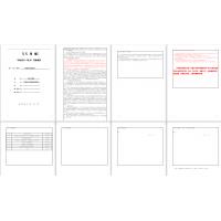 机械设计制造及其自动化毕业设计(论文)开题报告...¥0
 XX大学理工类毕业设计(论文)开题报告——自行车配件管理系统...¥0
 课程设计 CA6140车床拨叉831002的加工工艺及钻φ25孔的钻床...¥0
 补价¥1.00
 毕业设计辅助工具_免费在线论文文案文章修改神器_毕业设计辅助软件_AI...¥0
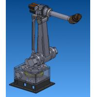 六自由度工业机器人设计【说明书(论文)+CAD图纸+SolidWork...¥45.00
 陈家沟桥梁施工组织设计方案.doc...¥0
摘要
本设计的题目为某中级轿车前轮制动器设计,本设计选用前轮盘式制动盘式制动器分为定钳盘式和浮钳盘式。在充分了解制动器的结构及工作原理的基础上借助多方面的资料进行设计、论证再选定相关参数并进行计算确定具体参数如下:
制动力分配;前轴制动力Fu1=4486.3 N 后轴制动力 Fu2=9405.2 N
同步附着系数;=0.7
制动器效能因数;k=0.6
制动力矩:制动力矩是制动器产生的,迫使汽车减速或停止的阻力矩,由该车所能遇到的最大附着系数;制动强度q;车轮有效半径;汽车满载质量G;汽车轴距L;通过计算得出:前轮的制动力矩为Mu1=1358.15 N·m 后轮制动力矩Mu2=497.2 N·m
由以上参数进行设计计算确定主要零部件尺寸和制造材料最后对制动系统性能要求进行校核,并用solidworks三维软件绘制出制动器零件的零件模型和制动器装配模型。
关键词:制动性能 solidworks 盘式制动器
Abstract
The topic of this design for the design of the front wheel brake a intermediate car,this design selects the front disc brakedisc brake caliper disc is divided into fixed and floating caliper.On the basis of understanding the structure and working principle of the brake,with various materials to design,demonstrate the selected parameters and the calculation to determine the specific parameters are as follows:
The braking force distribution;front axle braking force Fu1=4486.3 Nthe rear axle braking force Fu2=9045.2 N.
The synchronous adhesion coefficient: =0.7
Brake effiency factor:k=0.6
Brake torque:Brake torque is generated by the brake, torque force car to slow down or stop,maximum adhesion coefficient can meet the vehicle ;severity of braking q;the effective radius re;The car loaded with quality G;the vehicle wheelbase L;calculation the front wheel brake toeque Mu1=1358.15 N·m,the rear wheel brake toeque Mu2=497.2 N·m
The design calculation of main parts size and material from the above parameters,the brake system performance requirements of applications,and use SolidWorks software to draw the parts of 3D model and the brake brake parts model.
Keywords: braking performance solidworks disc brake
目 录
第一章绪论1
1.1制动系统设计的意义1
1.2 制动器的发展历程1
1.3 国内汽车盘式制动器的应用2
1.4 国外汽车盘式制动器的应用3
1.5 目前制动器的发展现状5
第二章 制动器的结构与设计原则11
2.1 汽车制动系功用及分类11
2.2 盘式制动器的分类与介绍11
2.3 盘式制动器的结构与工作原理14
2.4 制动器设计的一般原则15
2.4.1 制动效能16
2.4.2 制动效能稳定性16
2.4.3 制动间隙调整简便性16
2.4.4 制动器的尺寸及质量16
2.4.5 噪音的减轻17
第三章 制动器设计18
3.1 主要设计参数18
3.2 盘式制动器主要元件18
3.2.1 制动盘18
3.2.2 制动块20
3.2.3 制动钳21
3.2.4 衬块报警装置设计22
3.2.5 摩擦材料22
3.2.6 制动器间隙及调整22
3.3 制动器制动力分配分析23
3.4 同步附着系数的选取23
3.5 制动器效能因数25
3.6 制动器制动力矩的计算25
3.7 制动系统性能要求25
3.7.1 制动时汽车的方向稳定性的要求26
3.7.2 制动减速度的要求26
3.7.3 制动距离的要求27
3.7.4 制动力矩的要求27
3.7.5 对车轮制动器的比能量耗散率的要求27
3.7.6 对比摩擦力的要求27
3.7.7 对热流密度的要求27
3.7.8 对衬块吸收功率的要求27
3.7.9 对平均摩擦力的要求28
3.7.10 行车制动至少有两套独立的驱动器的管路28
3.7.11 防止水和污泥进入制动器工作表面28
3.7.12 要求制动能力的热稳定性好28
3.7.13 操纵轻便28
3.7.14 紧急制动时踏板力的计算28
3.7.15 制动踏板行程的计算29
3.7.16 其他29
3.8 摩擦衬片的磨损特性29
第四章 校核32
4.1制动器的热容量和温升的核算32
4.2.1 制动盘的技术要求32
4.2.2 制动钳技术总成要求33
4.2.3 前轮轮毂总成技术要求33
结论………………………………………………………………………………….35
参考文献…………...…………………………………………………………… ...36
致谢……………………….………………………………………………………... 38
知识产权声明………………...…………………………………………………..39
独创性声明……………………………………………………………………..…40
………………


