 毕业设计辅助工具_免费论文文案文章修改神器_毕业设计辅助软件_论文查重...¥0
 solidworks2018 中文版¥0
 CA6140车床拨叉831006零件夹具设计说明书——9页...¥0
 机械设计制造及其自动化毕业设计(论文)开题报告...¥0
 XX大学理工类毕业设计(论文)开题报告——自行车配件管理系统...¥0
 课程设计 CA6140车床拨叉831002的加工工艺及钻φ25孔的钻床...¥0
 补价¥1.00
 毕业设计辅助工具_免费在线论文文案文章修改神器_毕业设计辅助软件_AI...¥0
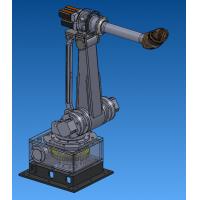 六自由度工业机器人设计【说明书(论文)+CAD图纸+SolidWork...¥45.00
 陈家沟桥梁施工组织设计方案.doc...¥0
目 录
2 Load calculation, reactive power compensation, and the choice of the main transformer
2.1.2 Total load reactive power
2.2 Reactive power compensation
2.2.1 Need to compensate reactive power
2.2.2 Reactive power compensation equipment
2.4 The selection of the transformer
2.4.1 The main transformer stations
2.4.3 The determination of winding number and connection group
2.4.4 The choice of the ways of regulating
2.4.5 The choice of the ways of cooling
2.4.6 The capacity of transformer
2.4.7 The model of the transformer
3 The electricity wiring design and the choice of transformer is used
3.1 The determination of variable volume and the Numbers
3.2 The electricity connection mode
4 The choice of the main electrical wiring
4.1 The basic requirement of design
4.2 The principle of design of main wiring
4.3.1 The connection of 35 kv side
4.3.2 The connection of 6 kv side
5 Short circuit current calculation
5.1 The purpose of short-circuit current calculation
5.3 Short circuit calculation parameter table
6 Main electrical equipment selection and calibration
6.1 35 kv bus bar of choice and check
6.2 The choice of 35 kv high voltage circuit breaker and check
6.3 35 kv disconnecting switch, selection and verification
6.4 35 kv current transformer selection and calibration
6.5 The choice of 35 kv and 6 kv voltage transformer and check
6.6 The choice of the high voltage switch cabinet
6.7 The choice of 6 kv switch cabinet
6.7.3 Distribution circuit breaker switch cabinet
6.7.4 With current transformer switchgear
6.8 6 kv load distribution for choice
